PCBs Arrived: First Board Assembled #
March 2026
GardenBotHardwareElectrical
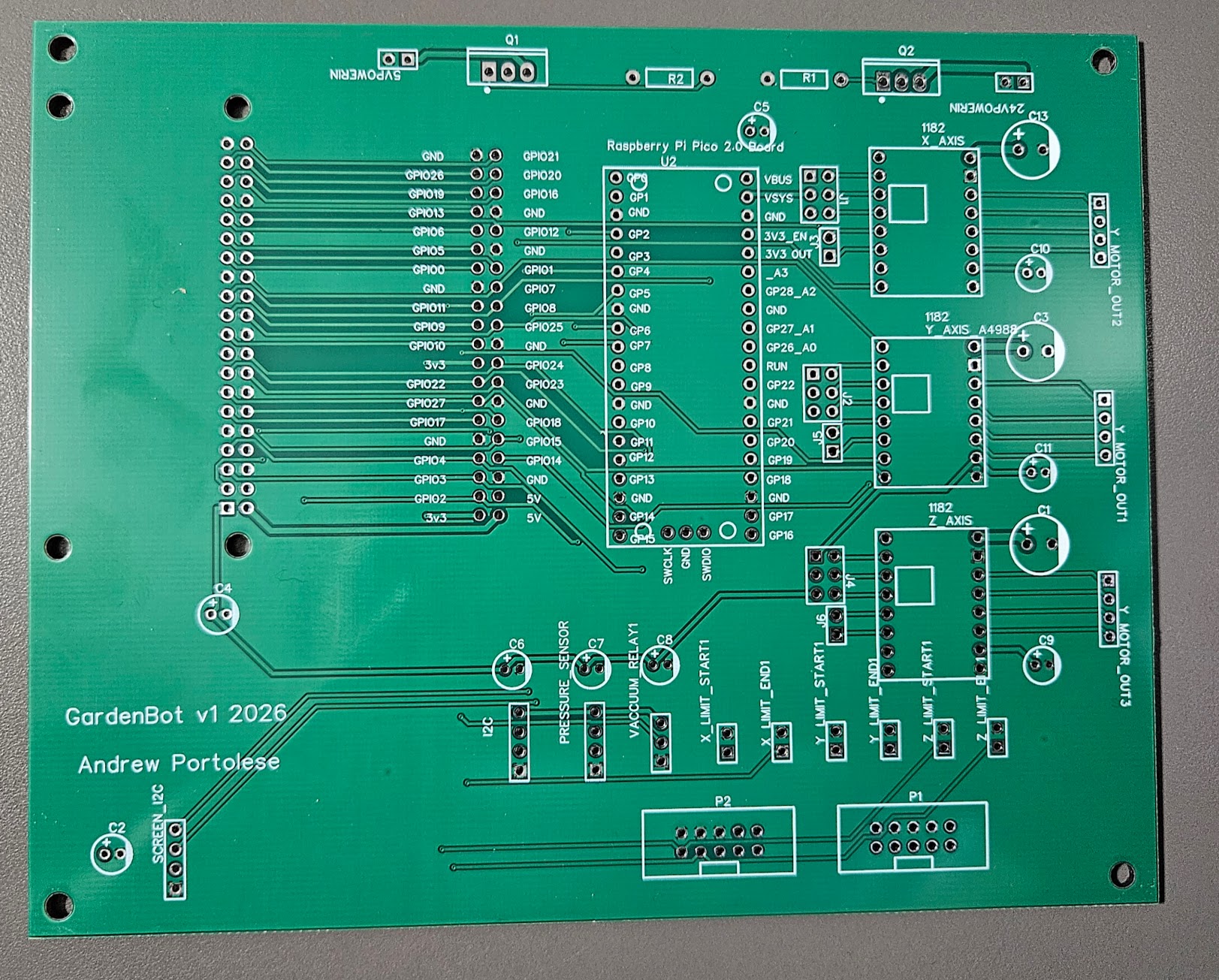
The boards came in from the fab house, and holding them for the first time was something else entirely. Seeing your own circuit design manufactured on real FR4 — copper traces, silkscreen labels, solder pads all exactly where you placed them — hits different than looking at it on a screen. This is the GardenBot v1 main board: the first PCB I've ever designed and had fabricated. "GardenBot v1 2026 — Andrew Portolese" printed right on the silkscreen.
Soldering It Up
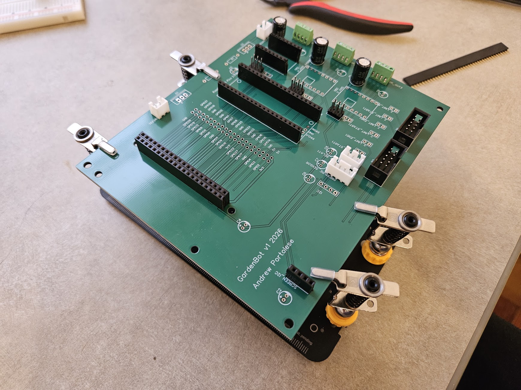
I worked through the board methodically — the microcontroller header first , stepper driver sockets, and finally the signal connectors. Through-hole soldering is straightforward if you're patient: heat the pad and the lead together, feed solder into the joint, and let surface tension do the work. Every joint gets inspected for cold solder or bridges before moving to the next component. The decoupling capacitors went in near each IC, the bulk caps near the stepper motor drivers, and the pin headers for the stepper drivers and I2C bus got seated flush against the board.
Fully Populated
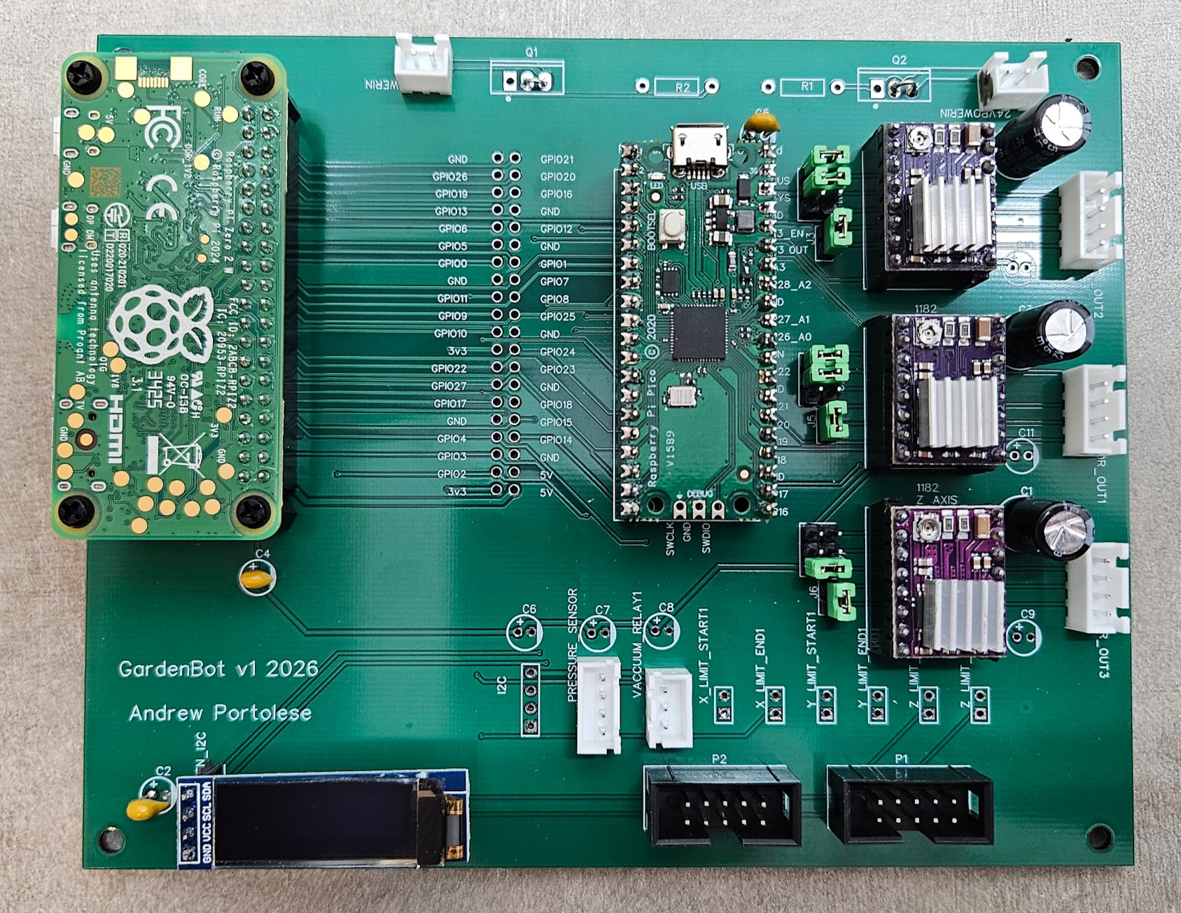
Every component seated, every joint inspected. The Raspberry Pi Pico 2 W plugs into its header at the top, the three DRV8825 stepper drivers slot into their sockets, the OLED display connects at the bottom, and the I2C and limit switch headers line the edges. The board looks exactly like the layout in EasyEDA — except now it's real.
The Workbench
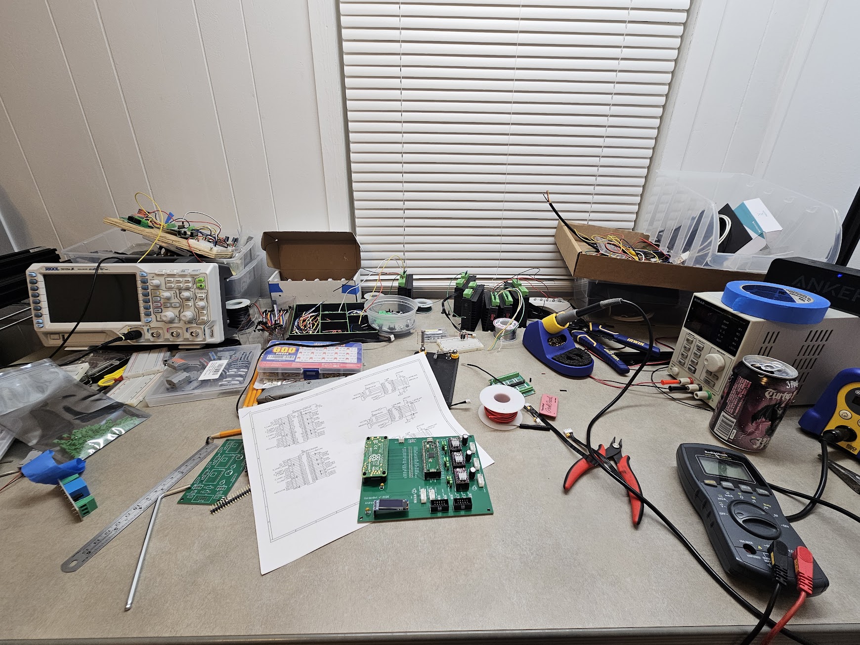
This is what the process actually looks like: oscilloscope, multimeter, solder reel, wire cutters, printed schematics spread out for reference, and the board sitting in the middle of it all. Every trace gets verified against the schematic with the multimeter before power-on. No shortcuts — a single bridged trace on a power rail can destroy components instantly.
From Schematic to Physical Reality
There's a moment when you power up a board you designed yourself and the voltage rails read exactly what they should. No magic smoke, no shorted traces, no footprint mistakes. Every connection that existed as a line in EasyEDA is now a real copper path carrying real current. The board went from a design file to a schematic to a Gerber export to a fab order to a physical object — and it works. The PCB is now wired into the GardenBot frame alongside the 24V power supply and vacuum pump, replacing the entire breadboard prototype.
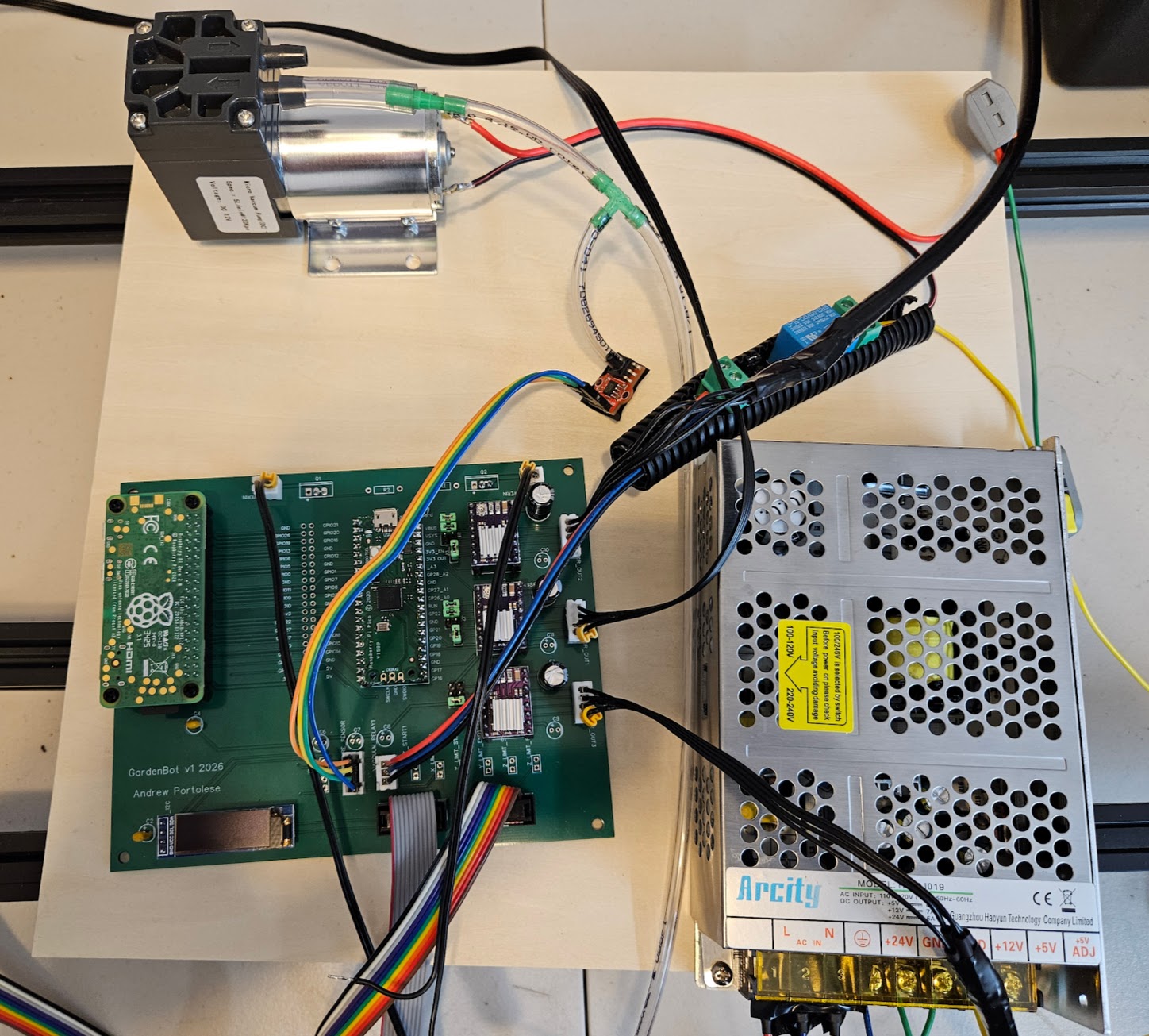
Going from breadboard prototyping to a manufactured PCB is a significant step in any hardware project. The breadboard validated the circuit design; the PCB makes it permanent, compact, and reliable. No more loose jumper wires, no more intermittent connections from a bumped table.
The hardware is ready to rock and roll. Everything is moving — all three axes are driving, the sensors are reading, and the vacuum is firing. Now it's time to dial it all in and start doing some real test runs.
Breadboard Prototype: Waiting on PCBs #
March 2026
GardenBotHardwareElectrical
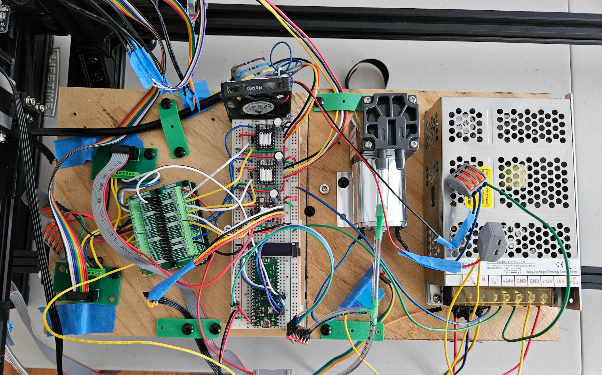
The full prototype is wired up on the breadboard and running — Raspberry Pi Zero 2 W, three stepper drivers, six limit switches, I2C sensors, and the vacuum relay, all validated and communicating. Breadboarding is an essential phase of any hardware project: it lets you iterate on the circuit design, test signal integrity, and verify every connection before committing to a PCB. The custom circuit boards are ordered and on the way.
From Soldering Kits to Circuit Board Design: A Childhood Dream Realized #
March 2026
GardenBotElectricalHardware
Growing up, I was always fascinated by electrical engineering. I'd take apart anything with a circuit board just to see what was inside. I practiced soldering and worked through electronics kit projects — learning how components fit together, how current flows, and how to read basic schematics. It was the thing I wanted to do before I ever wrote a line of code. But life took me down the software path first, and for years, the hardware side stayed on the shelf.
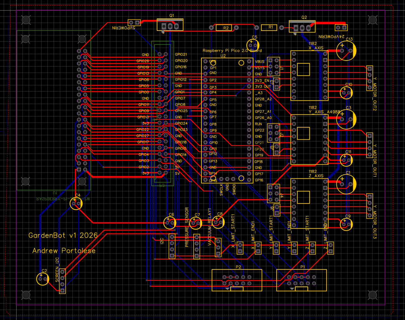
Now, with the GardenBot project, I'm finally circling back to that childhood interest. Except this time, I'm not just assembling kits — I'm designing my own circuit boards from scratch. The GardenBot v1 board is the first PCB I've designed, and it ties together everything the robot needs: a Raspberry Pi Pico 2 W, three A4988 stepper motor drivers, limit switch connectors, I2C bus headers, a vacuum relay output, and power regulation for both 5V and 24V rails.
The Main Board: GardenBot v1
The main board routes all connections from the Raspberry Pi Pico 2 W to the rest of the system. The GPIO pins fan out to stepper driver modules, limit switch headers, I2C peripherals, and the vacuum relay. Decoupling capacitors sit near every IC to filter power supply noise — a lesson I learned the hard way from breadboard prototyping where motors would cause brownouts on the logic side.
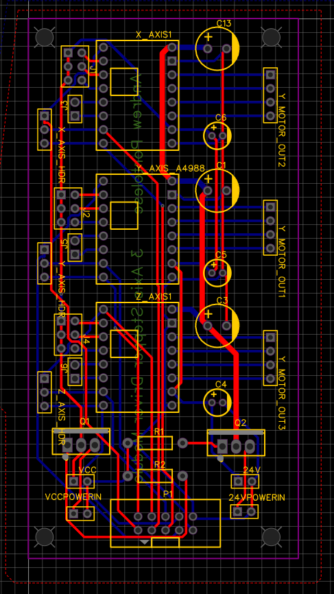
The 3-Axis Stepper Driver Module
This board isn't part of the GardenBot — the GardenBot's stepper drivers are integrated directly on the main board. But I had already designed a standalone 3-axis stepper driver module as a separate exercise, so I included it in the same PCB fabrication order. It holds three A4988 stepper drivers for X, Y, and Z axes, each with its own bulk capacitor for the motor supply, and consolidates the step/direction/enable signals into a clean header. The 24V motor power and 5V logic power come in through dedicated connectors with proper trace widths for the current draw. It's a reusable module for future projects that need multi-axis stepper control.
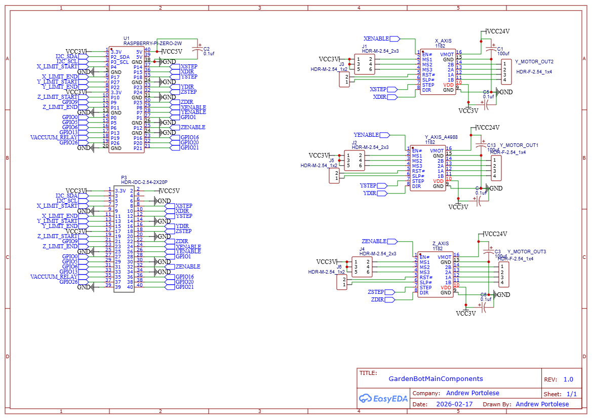
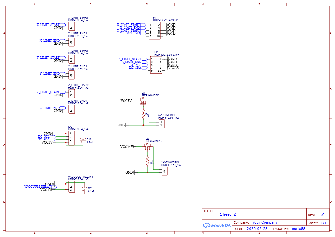
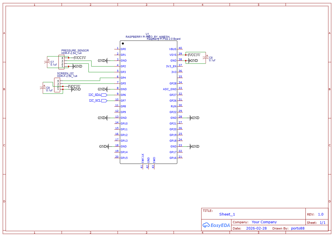
Schematics
I used EasyEDA for the schematic capture and PCB layout. The schematics are split across three sheets: main components (Raspberry Pi Pico, GPIO expander, stepper driver connections), connectors (limit switches, I2C bus, power inputs, vacuum relay), and the pressure sensor sub-circuit (Pico-based I2C slave for the HX710B).
Key lesson: Sometimes the long way around is the right way. Years of software engineering gave me the discipline to plan, debug systematically, and think in abstractions — skills that translate directly to circuit board design. The kid who just wanted to solder things together is now designing PCBs, and the software engineer is making sure the schematics are version-controlled and the designs are modular. Both halves of the journey matter.
Automated Seed Placement: The Farm Planner Algorithm #
February 2026
GardenBotAlgorithmsSoftware
Given N seeds of a certain type, the farm planner needs to find valid planting locations across multiple farmable regions, respecting minimum spacing between plants, then generate the CNC command sequence to plant them all. The algorithm runs in two passes.
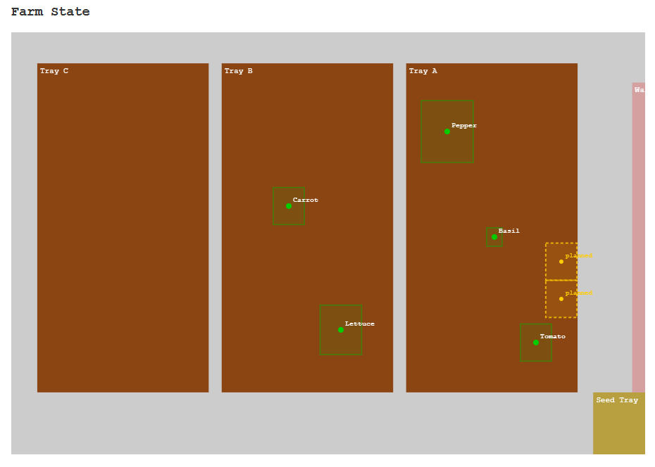
Pass 1: Greedy Grid Scan
The planner sweeps each region left-to-right, top-to-bottom, checking rectangular collision zones against existing plants. The spacing is rectangular rather than circular because the tool head is square — a physical constraint that changes the math compared to a pure software problem. The grid step size adapts to the seed type's space requirements.
Pass 2: Redistribution
After initial placement, seeds may be scattered across many regions. The redistribution pass consolidates them — taking seeds from sparse regions and placing them in denser ones. This means fewer tool head traversals during planting, which saves time and reduces mechanical wear.
Command Generation
For each seed location, the planner generates a command sequence: move to the seed tray, vacuum pickup, move to the target location, dig to the correct planting depth, release the seed. Plant locations are stored as region-relative coordinates, but CNC commands need absolute positions — the coordinate transform accounts for the farm's start offset and each region's bounds.
Key lesson: Physical-world algorithms need to account for things software algorithms don't — spacing constraints are shaped by the tool, coordinate systems flip between storage and execution, and the generated plan must be mechanically executable with no impossible tool paths.
Non-Blocking Motion Control: Running 3 Stepper Motors Without Threads #
February 2026
GardenBotSoftwareAlgorithms
The GardenBot has three axes that need to move simultaneously — X, Y, and Z steppers all running at different speeds with trapezoidal acceleration profiles. But you can't use blocking sleep() calls or dedicate a thread per motor, because the motion loop also needs to check limit switches, the e-stop channel, and vacuum pressure sensors between every step pulse.
Cooperative Multitasking with AccelStepper
I ported the AccelStepper library from C++ through MicroPython to standard Python 3. It implements David Austin's algorithm for generating stepper motor speed profiles in real time. The core pattern is a run_all() function that calls each stepper's run() method in a tight loop. Each run() checks if it's time for the next step based on mathematically computed intervals — no sleep, no threads, no timer interrupts.
The motion loop interleaves safety checks between step computations: e-stop monitoring via the MQTT priority channel, limit switch polling on all 6 endpoints, and vacuum pressure readings for seed detection.
Key lesson: Cooperative multitasking (polling) beats threading for real-time motor control. It's simpler, deterministic, and lets you interleave safety checks between every step pulse.
Why I Had to Add a Second Microcontroller to Read a Pressure Sensor #
February 2026
GardenBotHardwareSoftware
The HX710B barometric pressure sensor detects whether the vacuum nozzle has successfully picked up a seed. I started with it wired directly to the Raspberry Pi Zero 2 W, but the readings were unreliable. The sensor requires bit-banging a precise clock signal to read 24 bits of data, and Python on Linux simply cannot provide that level of timing precision. Linux scheduling jitter varied the clock pulse timing enough to corrupt the data stream.
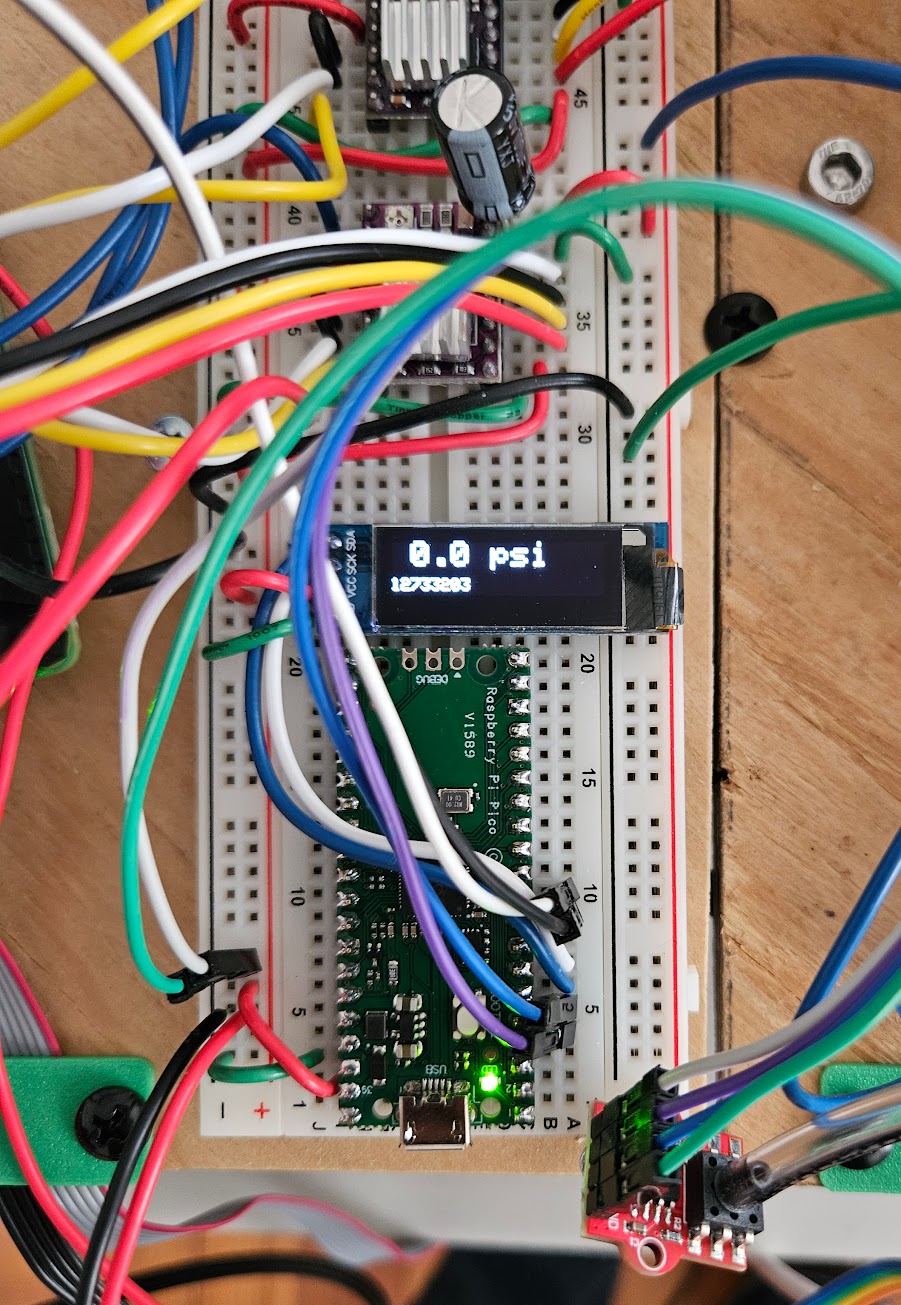
The Solution: Distribute the Work
I offloaded the sensor to a Raspberry Pi Pico ($4) running Arduino C++, which has deterministic timing with no OS scheduler to interfere. The Pico reads the HX710B continuously via bit-banging and exposes the latest reading over I2C as a slave device at address 0x08. The RPi Zero simply reads 4 bytes from the I2C bus — no timing-critical code needed on Linux.
It Wasn't That Simple
The Pico's MbedI2C library had broken I2C slave support on the RP2040 chip. I switched to the Earle Philhower arduino-pico core's native Wire1, which has proper slave mode. Then I discovered that raw i2c_rdwr() reads from the RPi side timed out — the Pico wasn't responding to bare read requests. The fix was switching to read_i2c_block_data() which sends a register byte first, and adding an onReceive handler on the Pico to consume that byte before the read request triggers onRequest.
Key lesson: Real-time sensor protocols don't belong on a general-purpose OS. Know when to delegate to dedicated hardware. A $4 Pico solved what no amount of Python optimization could.
From ESP32 to Raspberry Pi: Migrating a Robot's Brain Mid-Project #
February 2026
GardenBotSoftwareHardware
The GardenBot originally ran on an ESP32 with MicroPython. It worked for basic motion control, but I hit a ceiling — MicroPython's threading model was limited, the library ecosystem was sparse, and debugging through a serial console was painful. I decided to migrate the entire firmware to a Raspberry Pi Zero 2 W running standard Python 3.
What Had to Change
machine.Pin became gpiozero (InputDevice/OutputDevice)- Raw I2C became
smbus2 with a custom scan helper function
umqtt.simple became paho-mqtt with background threading via loop_start()- The AccelStepper library was ported twice: C++ to MicroPython, then MicroPython to Python 3
What Broke
A threading race condition in the MQTT message queue carried over conceptually from the old platform. MicroPython lists aren't thread-safe, and the same pattern was unsafe in CPython too. I2C device initialization order also mattered differently — the PCF8574 GPIO expander needed to be ready before any pins could be created. WiFi went from being firmware-managed on the ESP32 to OS-managed on Linux, which was simpler but required a different connection check approach.
What Improved Immediately
The full Python 3 standard library was a game-changer — proper JSON handling, threading primitives, and logging. SSH debugging replaced the serial console. pip install replaced manually copying files over USB. OTA firmware updates went from USB flash to HTTP downloads. The migration paid for itself in debugging speed alone within the first week.
Key lesson: Migration is never just "swap the libraries." The platform's threading model, I/O timing, and system architecture all shift. But moving to a more capable platform paid for itself in debugging speed alone.
The Complete GardenBot Stack #
February 2026
GardenBotSoftwareHardwareElectrical
The GardenBot is built from six layers that work together — a web frontend, a Python server, an MQTT message broker, firmware running on a Raspberry Pi, stepper driver electronics, and the mechanical CNC frame itself. Here's how each layer fits together and what technologies live at each level.

Frontend
The web interface is built with vanilla JavaScript and HTML5 Canvas. It renders the farm layout, lets the user define plantable regions, and displays planned seed locations. A WebSocket connection streams real-time log messages from the robot so the user can monitor operations as they happen.
Server
A FastAPI server handles HTTP requests from the frontend and stores farm state and planting plans in PostgreSQL. It runs the farm planner algorithm to compute seed placement locations and generates the CNC command sequences. The server also bridges between the frontend (HTTP/WebSocket) and the robot (MQTT).
Communication
A Mosquitto MQTT broker handles all command dispatch between the server and the robot. Commands and responses are JSON objects with a type-safe protocol — every message has a defined schema so both sides know what to expect. MQTT was chosen over HTTP because it supports persistent connections, low-latency pub/sub, and works well over WiFi with intermittent connectivity.
Firmware
The Raspberry Pi Zero 2 W runs Python 3 firmware that parses incoming MQTT commands, dispatches them to the appropriate handler, and coordinates all hardware interactions. It manages the AccelStepper motion control library, reads sensors over I2C, monitors limit switches, and handles e-stop signals. The firmware supports OTA updates so I can push new versions over the network without touching the robot.
Electronics
DRV8825 stepper drivers convert GPIO step/direction signals into motor coil current for the X, Y, and Z axes. A PCF8574 I2C GPIO expander provides additional pins. Sensors include a VL53L4CD time-of-flight sensor for measuring distance to the soil surface and an HX710B pressure sensor (read by a dedicated Raspberry Pi Pico over I2C) for detecting whether the vacuum nozzle has picked up a seed. Limit switches on all six endpoints provide homing and safety stops.
Mechanical
The physical frame is a 3-axis CNC with lead screws converting stepper motor rotation to linear motion at 80.2 steps per millimeter. A vacuum pump with relay control handles seed pickup, and the tool head moves across the planting bed to place seeds at the computed locations.
Key lesson: Each layer has its own failure modes and debugging tools. Web bugs show up in the browser console, server bugs in Python logs, communication bugs in MQTT message traces, firmware bugs over SSH, and electrical bugs with a multimeter. Knowing which layer to look at is half the battle.
Seed Planting Robot #
January 2026
GardenBot
The goal is to build a 3-axis CNC robot that autonomously plants seeds in soil. The system will use a vacuum pump for seed pickup, a barometric pressure sensor to verify successful pickup, and stepper motors with limit switches for precise positioning across the planting bed. The project spans microcontroller programming (Arduino, ESP32, Raspberry Pi), CAD modeling, custom circuit board design, and motor/sensor/relay control.
The longer-term vision is to evolve this into an autonomous gardening robot — something like a Roomba for the garden — incorporating computer vision, AI-driven plant health monitoring, and adaptive planting strategies.
Exploring Robotics, SLAM, localization, image detection #
January 2026
SLAM/Vision
Links
Exploring Mechatronics #
January 2026
GardenBotHardware
Links
Arduino
ESP32
Raspberry Pi Zero 2 w
and Modules